| My Cart | My Acc. | Dealers | Index | ||||||
| Manuals | Affiliate |  |
Help |
|
|
|||||||||||||||||||||||||||||||||||
| Browse By Brands: | ||||||||||||||||||||||||||||||||||||
|
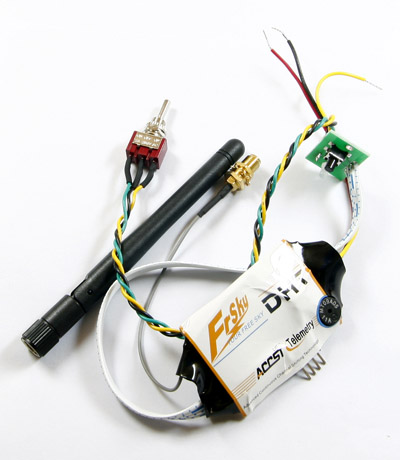
FrSky Two-way 2.4G DHT Module - Toggle Switch Version |
|
||||||||
|
||||||||||
| Tags: FrSky 2.4G 2.4GHZ two-way 2-way accst telemetry,DHT |
1.1 Compatibility:
| Switch 1 | Switch 2 | Mode of DHT | Compatibility |
| OFF | OFF | Two-way Mode | Two way telemetry receivers (D8R, D6FR) |
| OFF | ON | V8 Mode | V8 receivers (V8FR-HV, V8R7-HV, V8R7-SP, V8R4) |
1.2 Specifications:
Operating Voltage Range: 6.0V-13.0V
Operating Current: 50mA
Output Power: 60mW
Resolution: 3072 (>11bit)
2. Setup
2.1 Installation process:
1)Open the transmitter, find out Battery power supply line, PPM signal line, and GND.
2)Take the order and solder Battery power supply line, PPM signal line, and GND to DHT with 3 wires.
(RED→V+; BLACK→GND; YELLOW→PPM)
3)Drill one hole on the transmitter to install the PCB with F/S button, GREEN/RED LED and two switches.
4)Connect the antenna connector at the port on transmitter board.
5)Drill a hole for antenna connector at suitable space on the transmitter (diameter 7mm is suitable).
6)Fix the transmitter antenna on the connector .Turn the transmitter power on and check the power indicator LED, which is normally light RED.
2.2 Bind procedure
1)Turn your transmitter on and switch it to PPM mode. Turn your transmitter off.
2) Turn your transmitter on while holding the F/S button on the transmitter module (Please make sure DHT is in its corresponding mode when working with V8 or two way telemetry receivers). Release it in a few seconds. The RED LED on the transmitter module will flash, indicating the transmitter is ready to bind the receiver.
3)Connect battery to the receiver while holding the F/S button on the receiver. The RED LED on the receiver will flash, indicating the binding process is completed.
4)Turn on the transmitter and re-connect battery to the receiver. The RED SOLID LED on the receiver will indicate the receiver is receiving commands from the transmitter.
5)After the above steps are completed, both the transmitter and the receiver are ready to be used.
Notice: When working with two way telemetry receivers (D8R or D6FR), please kindly make sure that the battery and servos are plugged into CH1~CH8/CH1~CH6 rather than side port (A2/Rx), otherwise you will notice no function of the servos.
2.3 Range check
It is highly suggested to perform pre-flight range check. Caution must be paid when you perform range check in environment with metal fences, concrete buildings, or rows of trees. Loss of signal may be experienced from reflections.
Please kindly follow the steps below to perform range check: (Note: this should be done with the receiver installed in the model):
1) Place the model at least two feet (60cm) above non-metal contaminated ground (like wooden bench).
2) Place the receiver’s antennas apart. Do not let the antennas touch the ground.
3) Place the antenna of the transmitter in a vertical position.
4) Turn on the transmitter and receiver, press the F/S button of the transmitter for 4 seconds to enter range check mode, the RED LED of the transmitter module will be off, GREEN LED will flash rapidly, the BEEPER will sound. The effective distance will be decreased to 1/30 of full range.
5) Walk away from the model while simultaneously operating the controls on the transmitter, confirming that all controls are completely and correctly operated at least 30 meters away.
6) Press the F/S button for 1~4 seconds, the transmitter will exit range check mode. RED LED will be back on.
2.4 Signal loss indicator and failsafe setting
In some special circumstances, such as strong interference, the signal may be lost. When signal is lost in a short period, the receiver continues to try to search for the transmitter, at the same time it keeps the last command from the transmitter, until a new command is received.
FrSky receivers support failsafe function for all channels. Please kindly follow the steps below to set failsafe:
1) Bind the receiver first;
2) Set failsafe at any required position on any channel.
3) Press briefly the F/S button of the receiver (less than 1 second), DHT will make a long “beep” (when in its two way mode), indicating the failsafe position is remembered by the receiver.
If you do not need the failsafe function any more, just re-bind the receiver to set default failsafe mode.


|
©2003-2026 HiModel All Rights Reserved. |
|
|