| My Cart | My Acc. | Dealers | Index | ||||||
| Manuals | Affiliate |  |
Help |
|
|
|||||||||||||||||||||||||||||||||||
| Browse By Brands: | ||||||||||||||||||||||||||||||||||||
|
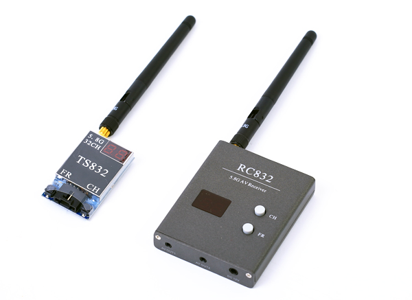
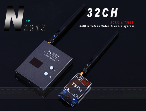
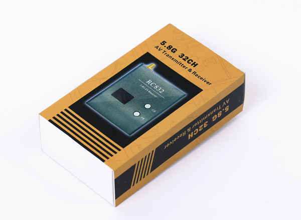
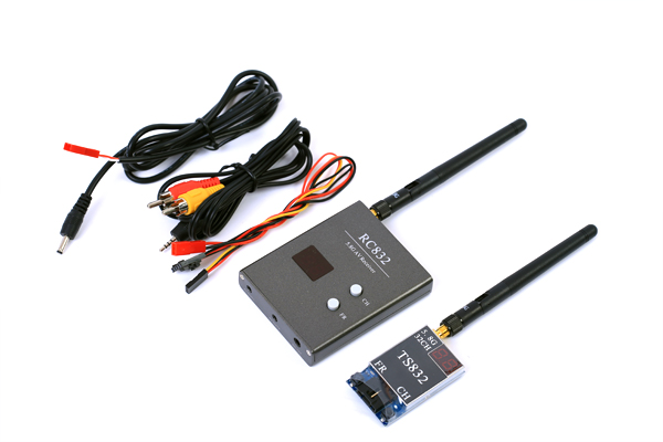
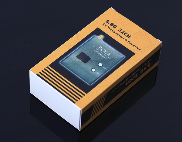
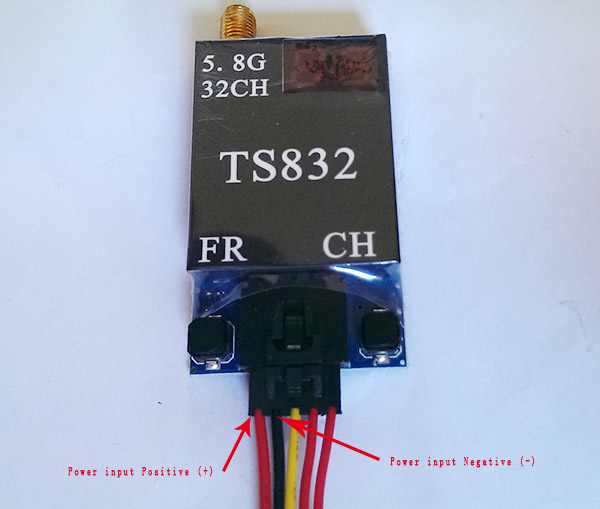
FPV 5.8G 600mW A/V Transmitting/Receiving System TS832 + RC832 - 40CH Edition | RP-SMA, jack |
|
||||||
|
||||||||
|
||||||||
| Tags: video recording system FPV 32 channels | ||||||||
|
©2003-2026 HiModel All Rights Reserved. |
|
|