| SKU | RT832T |
|---|---|
| Added | 2013/06/22 |
| Updated | 2013/08/21 |
Features:
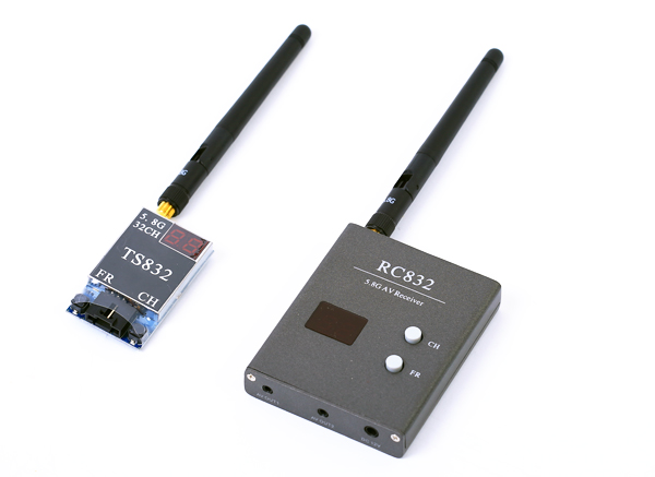
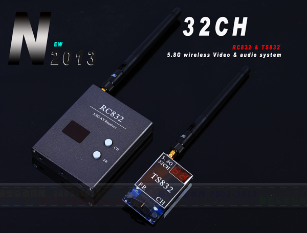
THIS IS THE NEW 32-CHANNEL EDITION OF 5.8G 600mW A/V WIRELESS SYSTEM.Features:
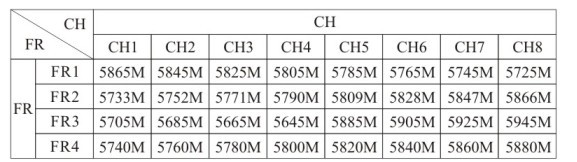
• 32 channels: Cover A, B, E bands and F band (Airwave band), 4 bands and all frequencies compactable;
• Two switching buttons: CH button for frequencies channels switching, FR button for frequencies bands switching;
• Two digits display: one for CH and the other for FR, real-time positioning which frequency band and which channel received;
• Power off memory: Replay the very last frequency band and channel
• Independent video and audio signal outputs
Specifications:
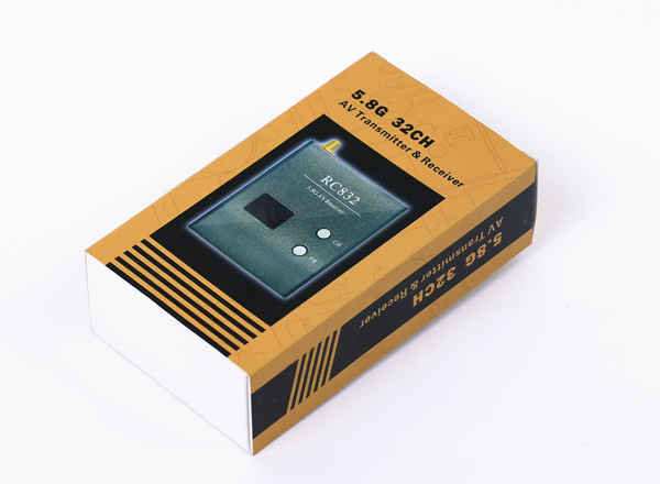
FPV 5.8G 600mW A/V Transmitting/Receiving System TS832 + RC832 - 32CH Edition | RP-SMA
video format supported: NTSC/PALAntenna connection: RP-SMA, jack (module side, both TX and RX) See connector type diagram
TX TS832 specs:
Power input: 7.4-16V (3S Lipo suggested)
Transmitting power: 600mA
Antenna gain: 2db
Working current: 220mA at 12V
Video bandwidth: 8M
Audio bandwidth : 6.5M
Weight: 22g
Dimension: 54x 32x 10mm(excluding antenna)
RX RC832 Specs:
Power input: 12V
Working current: 200mA max
Antenna impedance: 50Ω
Antenna gain: 2db
Video impedance: 75Ω
Video format: NTSC/PAL auto
Dimension: 80x 65 x15mm
Weight: 85g
*Note: TX antenna must be installed properly before it is switched on, power on without install antenna, or a improper antenna was used may easily burn the TX, and such damage is not covered by warranty.
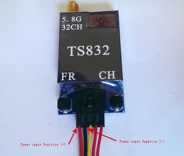
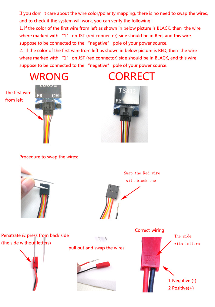
* We found that in recent batch, some of the TX TS-832 come with reversed power supply wires, the first wire from left side is black instead of red, but we also noticed that for the ones with reversed wires, the wires on JST connector side are also reversed, so in this case, if you connect the JST connector to a battery pack with standard polarity JST connector, as both the sides are reversed, so the system can still work properly, but in this case, the black wire is for "Positive" pole, and the red wire is for "negative". In other words, if the first wire from left on the TX module side is black instead of red, then on JST side, the black wire should be connected to the Positive pole of your battery.
The key point is that the first wire/pin from left side as shown on above diagram must be connected to "positive" pole of your power source, so if the wire color mapping is not critical for you, you can leave it without any change for the "wrong" cables, also this TX module with wrong polarity protection, it will not damage the TX even in case the power supply is in wrong polarity.
For the ones who concern about the color/polarity mapping issue too much, you can follow the below diagram to swap the wires:
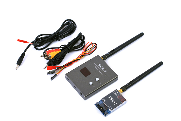
Includes/Requires:
Includes:1 x transmitting unit (TX)
1 x receiver (RX)
2 x antennas (2db)
1 x basic wires set