| SKU | TH-2AX |
|---|---|
| Added | 2014/04/04 |
| Updated | 2014/08/12 |
Features:
- Simple Rocker 1.2 Joystick controller- Control PICH and ROLL of gimbal controller Simple BGC through a universal joystick.
- Under PWM mode, PITCH output through PMW1, ROLL output through PMW2.
- Under serial port mode, signal output through serial port.
Specifications:
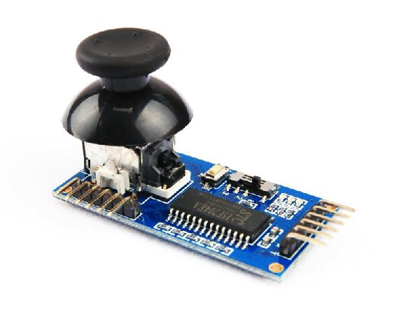
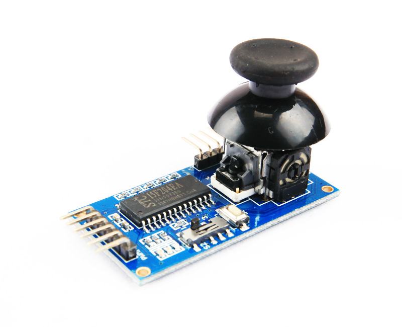
Joystick Controller Simple Rocker 1.2 for Handheld Brushless Gimbal (Main Board Only)
LED Signal Module
- Red LED: Power signal
- Green LED: IIC status. When IIC works normally, green LED light up. When IIC data error, green LED flashes. (Error data would not always effect the operation.)
- Blue LED: Start signal. When starting, blue LED flashes twice.
- Note: When serial port does not connect to BGC, green LED would not light.
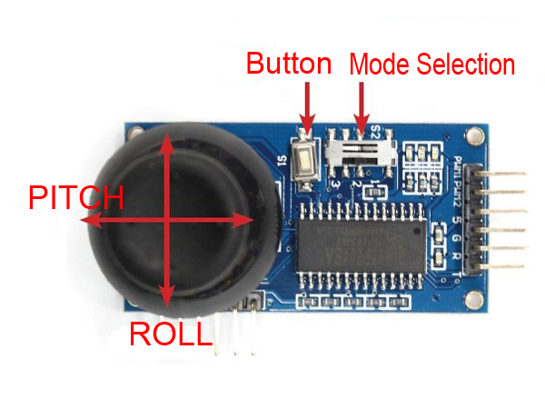
Mode Selection
- Note: This function is available when main board is used alone. This function is not available when main board assembled with extension board (NOT included).
- Turn on/off S2 through 3-way switch
- 3-way switch function as picture1:
1. PWM output mode
2. Serial port output mode (User needs to set BUAT rate 9600 through firmware)
3. No function - After mode selection, user needs to connect power again to start new mode.
Button
- 1. Calibrate ACC through serial port of S2.
- 2. Control camera output signal through built-in button on joystick of main board
- 3. Built-in button on joystick of extension board: no function
Description (Extension Board) (Not include and needs to be purchased separately)
- Simple Rocker 0.9 is the extension board for Simple Rocker 1.2.
- Output YAW through left-right control; Output camera signal through up-down control. (Applicable to camera focus and shutter trigger.)
- When main board assembled with extension board, the output interface is on main board. PMW1 and PMW2 are both output same signal- camera signal. ROLL, PITCH, and YAW are controlled through serial ports.
- Camera signal is usually turned off. Press the joystick on main board to activate output PWM, and release the joystick to turn it off.
Connect pin define: (Main board)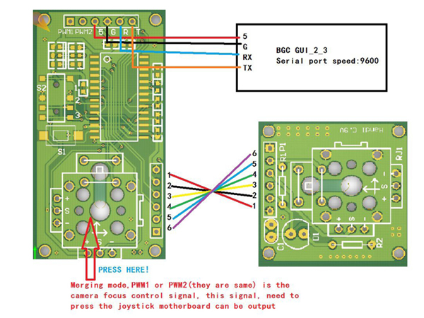
- From the left to the right: PWM1, PMW2, 5V, GND, R, T
- When using the main board alone with BGC, the connection is as below:
| BGC | remote control |
| 5V | 5V |
| GND | GND |
| T | T |
| R | R |
PWM mode connection:
| BGC | remote control |
| PWM1 | A0-A4 (or connect to PITCH) |
| PWM2 | A0-A4(or connect to ROLL) |
| 5V | 5V |
| GND | GND |
Description: PMW1 and PMW2 can be connected with any port from A0~A4. User just needs to set the corresponding interface from firmware.
Connect pin define: (main board connected with extension board)
Note:
1. After main board connected with extension board, please connect power again.
2. After connected with extension board, 3-way switch is not applicable to control selection. Control gimbal through serial port only. (User needs to set BUAT rate 9600 through firmware).
3. PMW1 and PMW2 are both output same signal. Select signal through up-down port of extension board. Default time 1.5ms high level, adjustable from 1ms~2ms. No output under normal circumstances unless pressing joystick of main board.
BGC firmware upgrade to 2.3
Upgrade firmware of BGC 2-axis from 2.2 to 2.3. Do nothing with the 3rd axis.
1. Activate SimpleBGC_2_3b5.enc.hex
2. Select FLASH to start installing
3. Successful installing balloon, connect controller board and set parameter according to your motor. (The parameter is varied according to different motors)
4. Connect to remote control, done!
Note:
Before connecting to controller, turn the 3-way switch to middle. Upgrade firmware only after connecting to power and blue LED stop flashing.
Recommended operation:
After adjusting parameter, disconnect power. Connect to controller, and connect power. After sensor initialization, green LED would stop flashing and light up, and upgrade.
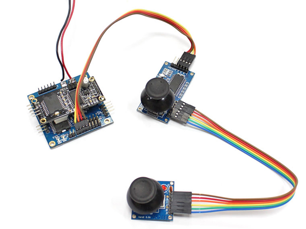
Application Sample (other parts are not included):
Includes/Requires:
Includes:1 x Joystick Controller main board
Requires:
1 x extension board
also software requirements as following:
PC software: SimpleBGC_GUI_2_3b4
PCB firmware for BGC: BGC2.3 (Upgrade BGC2.2 with SimpleBGC_GUI_2_3b4)